CANM8
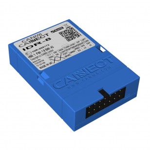
CanM8 CANNECT IDR8 8-Ausgangs-Canbus-Schnittstelle
CanM8 CANNECT IDR8 8-Ausgangs-Canbus-Schnittstelle
Verfügbarkeit für Abholungen konnte nicht geladen werden

Die CANM8 CANNECT IDR8-Schnittstelle bietet 8 der am häufigsten verwendeten Ausgänge bei Fahrzeugen mit CAN-Bus-Verkabelung.
Ausgänge - Standard IDR8
| Geschwindigkeitssignal | > | 12-V-Rechteckimpulsausgang mit ungefähr 4 Impulsen pro 1 MPH. |
| Zündung ein | > | 12 V (max. 1 A) bei eingeschalteter Zündung. |
| Linker Blinker | > | 12 V (max. 1 A), wenn der linke Blinker aktiv ist. |
| Rechter Blinker | > | 12 V (max. 1 A), wenn der rechte Blinker aktiv ist. |
| Betriebsbremse | > | 12 V (max. 1 A), wenn das Bremspedal gedrückt wird. |
| Abblendlicht | > | 12 V (max. 1 A), wenn das Abblendlicht aktiv ist. |
| Fernlicht | > | 12 V (max. 1 A), wenn das Fernlicht aktiv ist. |
| Seitenlichter | > | 12 V (max. 1 A), wenn die Seitenlichter aktiv sind |
Ausgänge - IDR8-R
| Geschwindigkeitssignal | > | 12-V-Rechteckimpulsausgang mit ungefähr 4 Impulsen pro 1 MPH. |
| Umkehren | > | 12 V (max. 1 A), wenn der Rückwärtsgang eingelegt ist. |
| Linker Blinker | > | 12 V (max. 1 A), wenn der linke Blinker aktiv ist. |
| Rechter Blinker | > | 12 V (max. 1 A), wenn der rechte Blinker aktiv ist. |
| Betriebsbremse | > | 12 V (max. 1 A), wenn das Bremspedal gedrückt wird. |
| Abblendlicht | > | 12 V (max. 1 A), wenn das Abblendlicht aktiv ist. |
| Fernlicht | > | 12 V (max. 1 A), wenn das Fernlicht aktiv ist. |
| Seitenlichter | > | 12 V (max. 1 A), wenn die Seitenlichter aktiv sind |
Anwendungen
Der CANM8 CANNECT IDR8 eignet sich ideal für den Einsatz mit Datenaufzeichnungssystemen oder für elektronische Geräte, die mehrere Signaleingänge benötigen. Alle Ausgänge (mit Ausnahme des Geschwindigkeitssignals) sind kurzschlussfest und auf 1 A ausgelegt.
Nach dem Kauf werden Sie kontaktiert, um das Baujahr/die Marke/das Modell Ihres Fahrzeugs zu ermitteln und die Schnittstelle richtig zu programmieren.
Installationsdetails
Die Schnittstelle verfügt über einen Mini-Kabelstecker, der sich zur einfachen Installation abziehen lässt. Es gibt zwei Anschlüsse zur CAN-Bus-Verkabelung des Fahrzeugs (CAN HI & CAN LO) sowie einen Anschluss an eine permanente, abgesicherte 12-V-Stromversorgung und einen Erdungsanschluss.
Die Schnittstelle verfügt über eine Multifunktions-Status-LED, die die korrekte Verbindung zum CAN-System, vorhandene CAN-Aktivität und die Bestätigung, dass die CAN-Identität erkannt wurde, anzeigt.
LED-Statusdetails
 |
Rot blinkend: Suche nach CAN-Informationen. |
 |
Durchgängig rot: CAN-Daten empfangen, aber Fahrzeug noch nicht identifiziert. |
 |
Durchgängig grün: CAN-Daten empfangen und Fahrzeugtyp erkannt. |
 |
Grün blinkend: Fahrzeuggeschwindigkeit erkannt. |
Kabelbaumdetails
| |
Verbinden Sie den Strom über eine 5A-Sicherung mit einem DAUERHAFT 12 V liefern. | |
| Anschluss an ein gutes Chassis BODEN Punkt. | ||
| CAN HI-Verbindung: Fahrzeug KANN HALLO Draht. | ||
| CAN LO-Anschluss: Fahrzeug KANN LO Draht. | ||
| Geschwindigkeitssignalausgang: 12 V pulsierend (4 Hz = ca. 1 MPH). | ||
| Zündung-Ein-Ausgang: 12 V (max. 1 A), wenn die Zündung eingeschaltet ist. | ||
| Ausgang linker Blinker: 12 V (max. 1 A), wenn der linke Blinker aktiv ist. | ||
| Ausgang rechter Blinker: 12 V (max. 1 A), wenn der rechte Blinker aktiv ist. | ||
| Betriebsbremsausgang: 12 V (max. 1 A), wenn das Bremspedal gedrückt wird. | ||
| Abblendlichtausgang: 12 V (max. 1 A), wenn das Abblendlicht aktiv ist. | ||
| |
Fernlichtausgang: 12 V (max. 1 A), wenn das Fernlicht aktiv ist. | |
| Standlichtausgang: 12 V (max. 1 A), wenn das Standlicht aktiv ist. |
Hinweis: Dieses Produkt wird direkt vom Hersteller versendet und die Lieferzeit kann 7–10 Werktage betragen.

