

CANM8
CanM8 CANNECT IDR8 8-Output Canbus Interface
CanM8 CANNECT IDR8 8-Output Canbus Interface
No se pudo cargar la disponibilidad de retiro
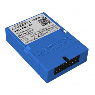
The CANM8 CANNECT IDR8 interface provides 8 of the most commonly used outputs on vehicles which feature CAN (Control Area Network) Bus wiring.
Outputs - Standard IDR8
| Speed Signal | > | 12v square pulsed output at approximately 4 pulses per 1 MPH. |
| Ignition On | > | 12v (1A max) when the ignition is switched on. |
| Left Indicator | > | 12v (1A max) when the left indicator is active. |
| Right Indicator | > | 12v (1A max) when the right indicator is active. |
| Service Brake | > | 12v (1A max) when the brake pedal is pressed. |
| Low Beam | > | 12v (1A max) when the low beam is active. |
| High Beam | > | 12v (1A max) when the high beam is active. |
| Parking Lights | > | 12v (1A max) when the parking lights are active |
Outputs - IDR8-R
| Speed Signal | > | 12v square pulsed output at approximately 4 pulses per 1 MPH. |
| Reverse | > | 12v (1A max) when reverse is selected. |
| Left Indicator | > | 12v (1A max) when the left indicator is active. |
| Right Indicator | > | 12v (1A max) when the right indicator is active. |
| Service Brake | > | 12v (1A max) when the brake pedal is pressed. |
| Low Beam | > | 12v (1A max) when the low beam is active. |
| High Beam | > | 12v (1A max) when the high beam is active. |
| Parking Lights | > | 12v (1A max) when the parking lights are active |
Applications
The CANM8 CANNECT IDR8 is ideal for use with Data Recording Systems or for any electronic device which requires multiple signal inputs. All outputs (with the exception of speed signal) are short circuit protected and rated at 1A.
Installation Details
The interface features a mini wiring connector, which unplugs to allow easy installation. There are 2 connections to the vehicle CAN Bus wiring (CAN HI & CAN LO) along with a connection to a permanent, fused 12v power supply and an earth connection. Purchase the contactless reader to prevent wire splicing of the CAN-specific wiring.
The interface incorporates a multi-function status LED, which indicates correct connection to the CAN system, CAN activity present and confirmation that the CAN identity has been recognized.
LED Status Details
- Flashing Red: Searching for CAN information.
- Solid Red: CAN Data received but vehicle not yet identified.
- Solid Green: CAN Data received and vehicle type recognised.
- Flashing Green: Vehicle speed detected.
Wiring Harness Details
| RED | > | Connect via a 5A fuse to a PERMANENT 12v supply. |
| BLACK | > | Connect to a good chassis GROUND point. |
| WHITE | > | CAN HI Connection : Vehicle CAN HI wire. |
| BLUE | > | CAN LO Connection : Vehicle CAN LO wire. |
| GREEN | > | Speed Signal Output : 12v pulsing (4 Hz = 1 MPH approx). |
| PURPLE | > | Ignition/Reverse On Output : 12v (1A max) when the ignition/reverse is switched on. |
| ORANGE | > | Left Indicator Output : 12v (1A max) when the left indicator is active. |
| BROWN | > | Right Indicator Output : 12v (1A max) when the right indicator is active. |
| PINK | > | Service Brake Output : 12v (1A max) when the brake pedal is pressed. |
| YELLOW | > | Low Beam Output : 12v (1A max) when the low beam is active. |
| GREY | > | High Beam Output : 12v (1A max) when the high beam is active. |
| BLUE (Untwisted) |
> | Side Lights Output : 12v (1A max) when the side lights are active. |
Notes:
- This product ships straight from the manufacturer and may take 7-10 business days to arrive after order is placed.
- Please enter your year, make, model of the vehicle you intend to use this device on in the space above. If this is not provided at time of purchase, you will be contacted to identify your year/make/model of vehicle to properly program the interface.